One of the most common problems regarding slitting is dust generation. Shear, crush, and razor slitting are all subjected to the causes of dust generation. Although dust amount is highly dependent on the material being slit, there could be other aspects affecting it. Including the set-up and equipment used, which can worsen this problem even further. As a result, it can start hurting the production line, especially when it comes to materials such as:
- Tissue
- Paper
- Sandpaper
- Non-wovens
- Fiber-glass
Something worth mentioning before we continue is that completely eliminating dust generation will never be possible. This is due to the nature and mechanics involved in slitting, regardless of the material and slitting method.
But, if you follow the guidelines and tips presented in this article, dust generation can and will be minimized. This article is the first of a three-part series on dust generation.
This topic is one of the most common problems in the industry. Our goal is to cover this topic as in-depth as possible. Explaining why and how some of the aspects of the slitting operation can impact dust generation.
What Causes Dust?
The answer: There are many contributing factors to dust generation.
- Blade set-up errors
- Poor-design
- Mechanical characteristics
- Web material itself
These are some of the causes that can lead to excessive dust generation. The starting point regarding slitting dust is to adhere to the geometric fundamentals:
- Cut Point
- Overlap
- Shear (cant) Angle
- Run-out
In this section, we will discuss how each geometric fundamentals of slitting affect dust generation. Except for Overlap, as this fundamental will have a section of its own, as it greatly affects dust generation.
Below are pictures showing these 4 fundamentals of slitting:
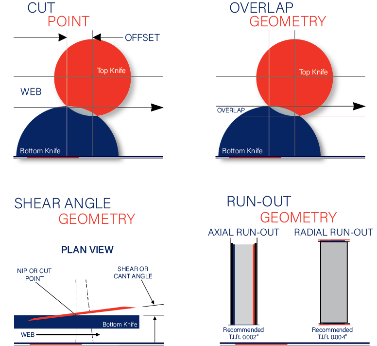
Common Causes of Dust Generation: Cut Point
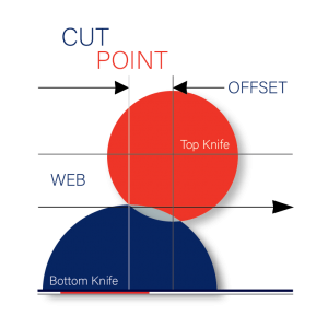
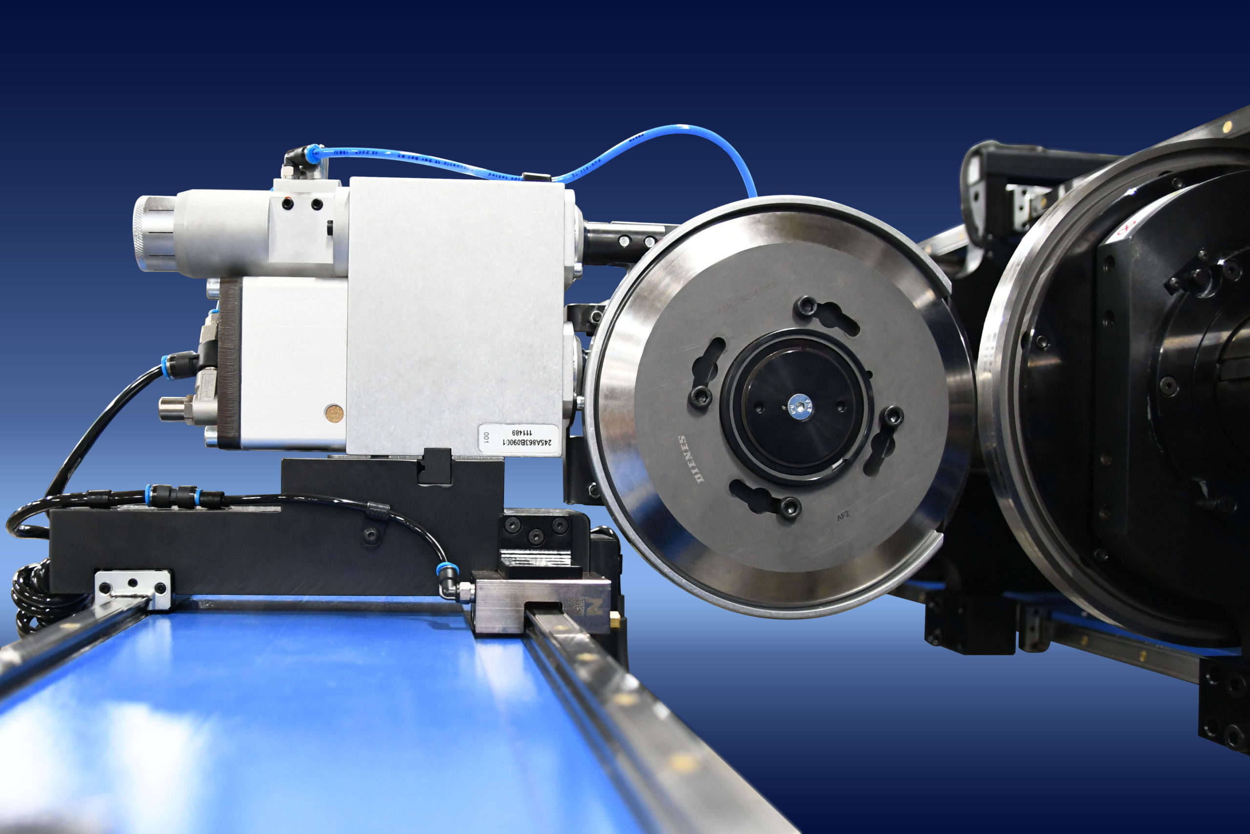
All shear slitting systems have a cut point design. Knife diameters and the web path (mounting locations set in the manufacturing and assembly drawings) are the bases for cut point. Unfortunately, operators have no control over the offset. The design process defines this, yet this is a critical element of controlling dust generation.
Although, the amount of web tension also plays a key role in limiting dust. Imagine a web is loose or floats into the slitter. The material will come in contact with the top (male) knife before the actual Cut Point. The web is then sawed as the blade “bursts” through it.
In conclusion, tension control is important to winding a perfect roll. It is also important for web slitting, controlling a clean roll edge, and limiting dust generation.
Common Causes of Dust: Shear Angle
In turn, the shear angle contributes to slitting dust generation by:
- the amount of planned angle
- the unplanned decreasing angle
- And as a cause of blade dulling.
One side of the slit material must travel across and around the angled blade. This by itself will cause damage to the web edge and contribute to dust.
The angle is set by the knife holder with a minimum of ¼, ½, or ¾ degrees. The knife degrees depends on the material. The steeper the angle, the more the web is disrupted after it is cut.
Knife Geometry Causes Dust
Various angles, shapes, and blade holder clearances can, and do, affect when and how much dust will occur. Knife geometry is the shape of the knife cutting edge.
Slitting performance can also be affected by the material of the knives. The effectiveness of the holder at maintaining the proper geometry relates to the design and ruggedness of the holder itself. Accuracy and consistency of setup, forces applied, and safety is affected by the setup procedures and tools themselves.
Manufacturing a knife holder with loose internal clearances can not maintain the planned shear angle. Applying the side load when contacting the bottom knife causes the loose components to shift until the clearance is taken up. A 0.0065″ looseness can remove a full ¼ degree of unplanned shear angle from some holders.
Unfortunately, not much can be done about this except for
- Maintaining the minimal shear angle
- By not using loose blade head holders
- Possibly looking at high chromium knife blade materials to keep the sharp edge as long as possible.
Run-Outs
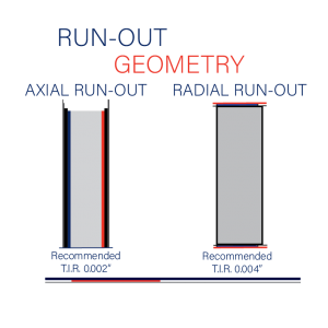
Finally, there are two types of run-outs affecting slitting and indirectly dust. The two include excessive axial run-out and radial run-out which, causes cyclic changes in overlap depth and blade thickness. Both will increase knife blade wear or dulling.
These run-out conditions can be the result of:
- Poor design
- Improperly manufactured
- Inadequately mounted
- Improperly reground tools.
- Inadequate or worn-out holder bearings,
- Worn-out vertical or horizontal pneumatic piston rods (guides),
- Poorly designed or worn-out knife mounting surfaces
Shaft driven bottom knives are susceptible to run-out based on knife O.D., width, and shaft mounting clearance. Cocking should always be avoided.
A simple axial run-out check is to mount and lock your bottom knives to the driven shaft. Then place a 0 to 0.010″ dial indicator against the bottom knife-edge. Slowly rotate the shaft while noting the maximum dimension change. The bottom knife O.D. is another location to put the dial indicator to measure radial run-out.
As we mentioned earlier in this article, this is only the first part of a three-part series. Make sure to come back for the second and most extensive Part 2: Dust generation caused by an incorrect overlap.
Follow us on LinkedIn or Facebook for similar articles like this one!
If you have any questions please feel free to contact us!
